RANDOM PAGE
SITE SEARCH
LOG
IN
SIGN UP
HELP
To gain access to revision questions, please sign up and log in.
GCSE
CD4017B
On the rising edge of the clock pulse, the next output goes high.
 Data Sheet
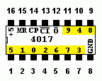
- The yellow numbered pins are the outputs from 0 to 9.
- Only one output is high at any given moment.
- On the rising edge of the clock pulse, the counter is advanced by one if CI is low.
- MR is the Master Reset to reset the whole chip. The output is reset to zero and pin three becomes high.
- CP is the clock pulse input.
- CI is the clock inhibit input.
- If CI is high, the counter stops counting but is not reset.
- If more than one counter chip is being used, the O output can be used to clock the next chip.
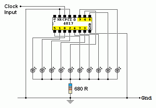
- The chip can drive LEDs with about 4 mA flowing. In a 5 Volt circuit, use 680Ω current limiting resistors.
Decade Counter
For the Falstad Circuit Simulation, CTRL+Click Decade Counter
In options, check European Resistors and uncheck Conventional Current.
LEDs Flash in Sequence
Alternatively view 4017_Dacade_Counter.txt.
Save or copy the text on the web page. Import the saved or copied text into the Falstad simulator.
Here is the new HTML5 Simulator Site.

reviseOmatic V3
Contacts, ©, Cookies, Data Protection and Disclaimers
Hosted at linode.com, London
 Data Sheet
